TTL Module
TTL Module Provides Error-Free Trigger Inputs and Strobe Outputs for PIXCI® Digital Frame Grabbers
TTL signal levels are often preferred for trigger inputs. The problem with TTL signaling is that it is single ended. Electrical noise coupled to the wiring changes the amplitude of the signal and can cause false triggers. The noise susceptibility is a function of the length of the wire.
The PIXCI® board series uses differential trigger inputs for the same reason that all digital cameras use differential signaling. Differential signaling is much less susceptible to noise.
THE DIFFERENTIAL ADVANTAGE - A differential signal uses a pair of twisted wires. Electrical noise will be picked up by both wires in the pair, but the differential receiver is triggered by the difference between the positive and negative signal inputs, while the noise will create a voltage that is the same to both wires in the pair. The differential receiver will not be affected by the noise.
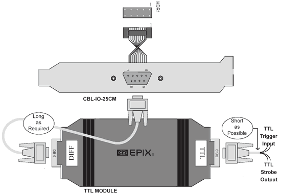
THE TTL MODULE CONSISTS OF 3 COMPONENT PARTS:
- A TTL-to Differential driver and printed circuit board with a protective plastic case.
- A CBL-D9-EXT-6FT extension cable (6 foot [1.82 Meter] Male / Female DB-9).
- A CBL-I/O-25CM ribbon cable with 10-pin header socket on one end, and Male DB9 connector on the other end (mounted in an expansion slot bracket). Note that the PIXCI CL1 Revision 2 and PIXCI SI boards feature an integrated CBL-I/O-25CM - they do not need this optional cable.
OPTIMIZED SIGNAL INTERFACE - The TTL module can be easily installed almost anywhere. It receives power from the PIXCI digital frame grabber eliminating the need for a dedicated power supply. A TTL module is configured to match the signal requirements of the supported camera: either area scan or line scan; either RS-644 or RS-422. EPIX must know the camera manufacturer and model number to configure the TTL module.
THE PRINCIPLE UNDERLYING THE PROPER USE OF THE TTL MODULE - The TTL conversion module should be positioned close to the TTL signaling device to keep the TTL cable to a minimum length. The differential cable should be as long as required to span the distance between the TTL conversion module and the PIXCI board, but less than 200 feet.
SCHEMATIC & CONFIGURATION


